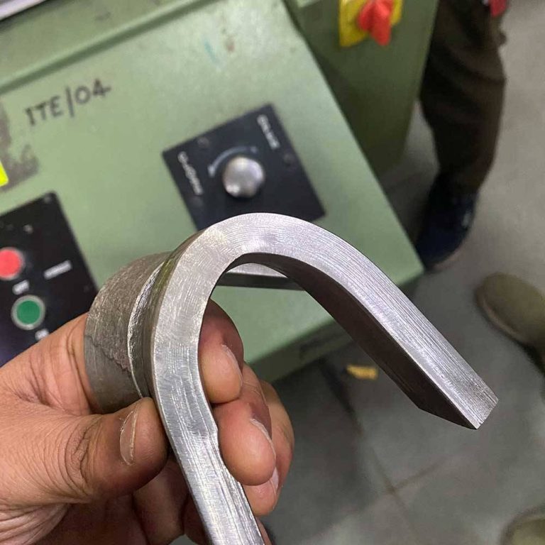





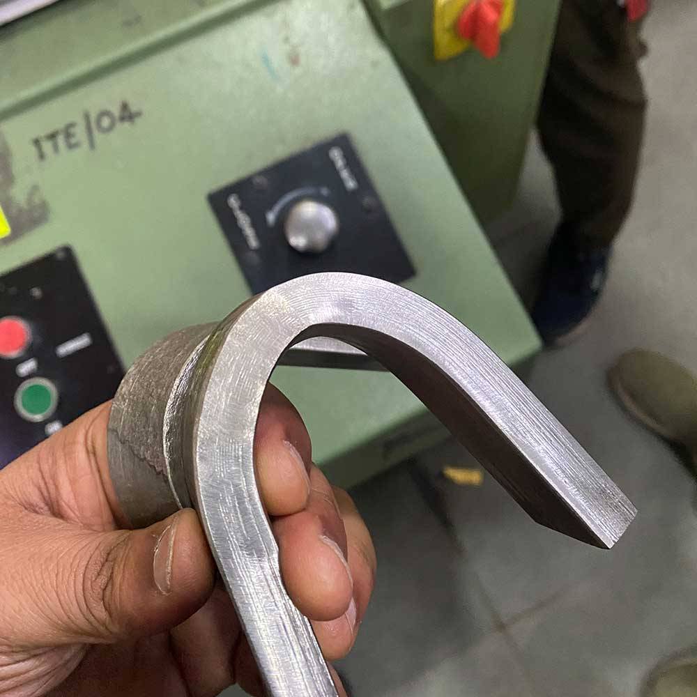
A bend angle determines the deformation level that the specimen will undergo. Thus, 90° and 180° bend tests are mutually exclusive tests.
The welding bend test determines ductility and the presence or absence of any cracking or discontinuity after controlled bending of a test specimen. The correct angle depends on the material, bend radius, and governing requirement.
Why Does Bend Angle Matter?
The angle defines how far the specimen deforms. 90° and 180° are different bend conditions. A larger bend angle is not necessarily a better test.
The bend radius matters too. ASTM E290-22 allows the bend test to end at a specified angle over a specified radius or continue until the specimen legs are in contact. The product requirements determine which condition applies.
What Does a 90° Bend Test Show?
A 90° bend subjects the specimen to defined plastic deformation. It can be appropriate when the applicable specification calls for that angle.
For welds, the test can help assess whether the welded area and surrounding material tolerate the required deformation without unacceptable cracking. The result must be judged against the acceptance criteria for the application.
What Does a 180° Bend Test Show?
A 180° bend creates a much greater change in specimen geometry. Depending on the method, the specimen may be bent until its legs approach or reach contact.
This condition can place substantial strain on the material and expose discontinuities that become visible during deformation. However, the test should not be described as universally more demanding or more informative. Its value depends on why the test is being performed.
90° vs 180°: What Is the Real Difference?
The key difference is the deformation condition required by the test procedure.
- 90°: A defined partial bend used where the applicable requirement calls for that condition.
- 180°: A much deeper bend that may bring the specimen legs toward contact.
- Both: Proper specimen geometry, bend radius, loading, and acceptance criteria are needed.
Professional Testing Services notes that bend angles are 90°, 120°, or 180° depending on the test standard. Three-point bend testing service is also offered by the company for materials and welds.
How Do Engineers Choose the Correct Angle?
Engineers do not normally select an angle based on preference alone. They first identify the applicable material or welding specification and then follow its required test method.
Important factors include:
- Material or weld type
- Specimen dimensions
- Bend radius
- Required bend angle
- Qualification or quality purpose
- Acceptance criteria
For welds, ASTM E190-21 covers guided bend testing for ductility and soundness. ASTM E290-22 covers bend testing of materials for ductility. Using the correct standard helps ensure that the test result has the intended meaning.
How Are Bend-Test Results Evaluated?
After the bending process, the sample is subjected to a visual inspection in order to check for any kind of cracks or defects on its surface. In a welding bend test, this inspection can provide evidence of how the weld responds to progressive deformation and whether unacceptable indications appear under the specified conditions.
The result is not simply “90° passed” or “180° passed.” Engineers must compare the observed condition with the governing specification. In other words, this will keep the test to its objective without making any assumption that a higher bend angle is better.
Choosing either 90 degrees or 180 degrees will come from the specification-driven decision. The right angle is the one that matches the intended test method, material, weld application, and acceptance criteria.